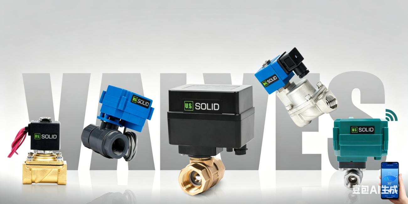
Choosing the right motorized ball valve is only half the battle; knowing how to wire it correctly ensures your automation system runs safely and efficiently. Unlike solenoid valves that require constant power to stay open, U.S. Solid motorized ball valves use energy only during motion, making them a high-efficiency choice for everything from DIY home automation to industrial fluid control.
In this guide, we break down the most common wiring configurations to help you get your system up and running in no time.
2-Wire Auto Return: Fail-Safe, Set & Forget
This is our most popular configuration for safety-critical applications. It operates like a Normally Closed (N.C.) valve—it opens when powered and automatically closes if power is lost.
- How it works: It uses a built-in capacitor to store energy.
- Wiring (DC): Connect Red to Positive (+) and Black to Negative (-). The valve opens. Disconnecting either wire triggers the auto-return to close.
- Wiring (AC): Connect one wire to Red and the other to Black.
- Pro Tip: For the auto-return to function, the valve must be powered for at least one minute initially to fully charge the capacitor.

2-Wire Reverse Polarity: Simple DC Switching
Perfect for simple DC systems where you can easily flip the direction of current (like using a DPDT switch).
- Open: Red (+) and Black (-).
- Close: Red (-) and Black (+).
- Behavior: If you disconnect the wires, the valve stays exactly where it is.

3-Wire Control: Precision Management
The 3-wire setup is ideal for systems where you want the valve to stay in its current position even if the control signal is lost.
- How it works: One common wire and two control wires (one for “Open,” one for “Close”).
- Wiring (DC): * Yellow is the Common/Negative (-) wire.
- Apply Positive (+) to Red to Open.
- Apply Positive (+) to Blue to Close.
- Wiring (AC): One terminal connects to Yellow; the other terminal switches between Red (Open) and Blue (Close).
- Benefit: Once the valve reaches its position, it stops drawing power entirely.

3-Wire (1-Way Setup): The Hybrid Approach
A specific configuration often used in specialized logic circuits.
- Open: Connect both Red and Yellow to Positive (+), and Blue to Negative (-).
- Close: Keep Red connected to Positive (+) and Blue to Negative (-), but disconnect the Yellow wire.

5-Wire Setup: Automation with Feedback
When you need your control panel to “know” if the valve is actually open or closed, the 5-wire model is the professional choice.
- Control (Yellow/Blue): Operates via reverse polarity (Positive/Negative for Open, vice versa for Close).
- Feedback Signal:
- Green + Black: Signal lights up when the valve is Fully Open.
- Red + Black: Signal lights up when the valve is Fully Closed.

Why Choose U.S. Solid Motorized Valves?
Our valves are engineered for durability and performance:
IP65/IP67 Rated: Dust-tight and protected against water jets, ensuring reliable performance in demanding environments.Energy Efficient: Consumes minimal power—typically 2W to 12W—only during operation ( valve travel time varies by model).Lead-Free & Safe: Constructed from certified materials such as Stainless Steel (SS304/SS316) or UPVC, suitable for potable water and chemical applications.